
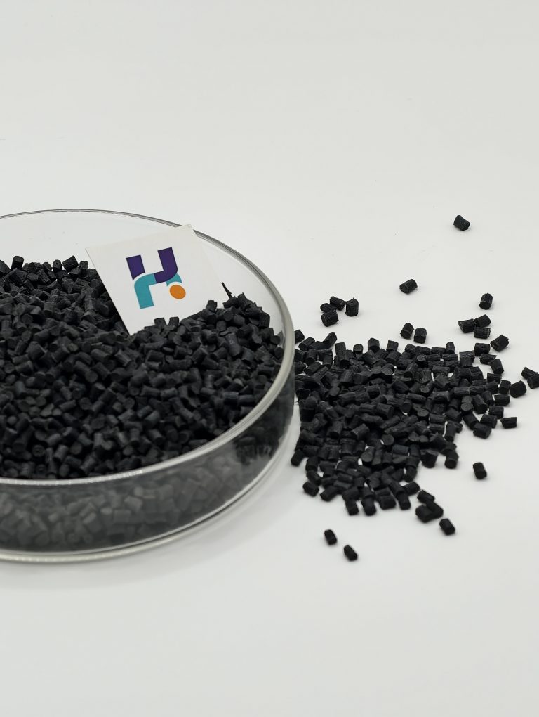
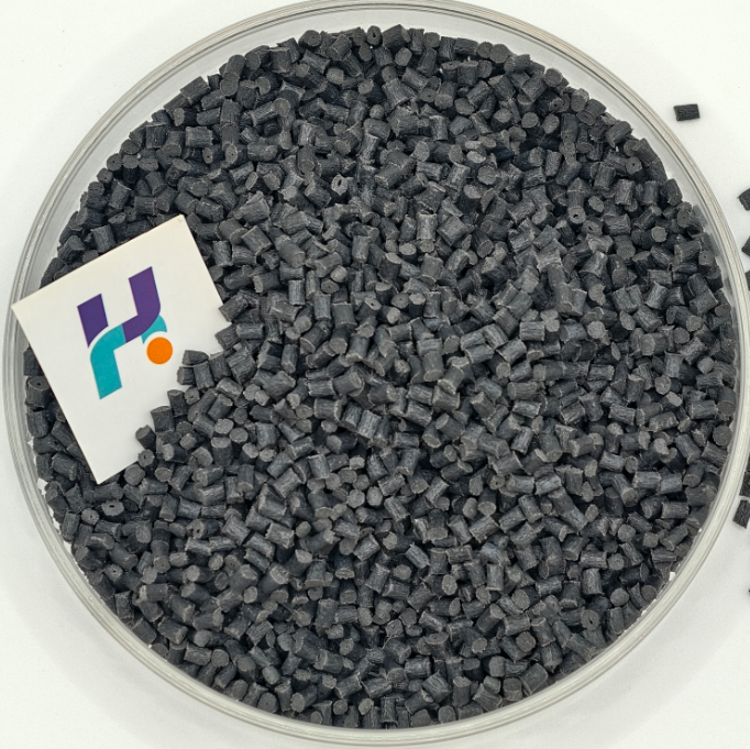
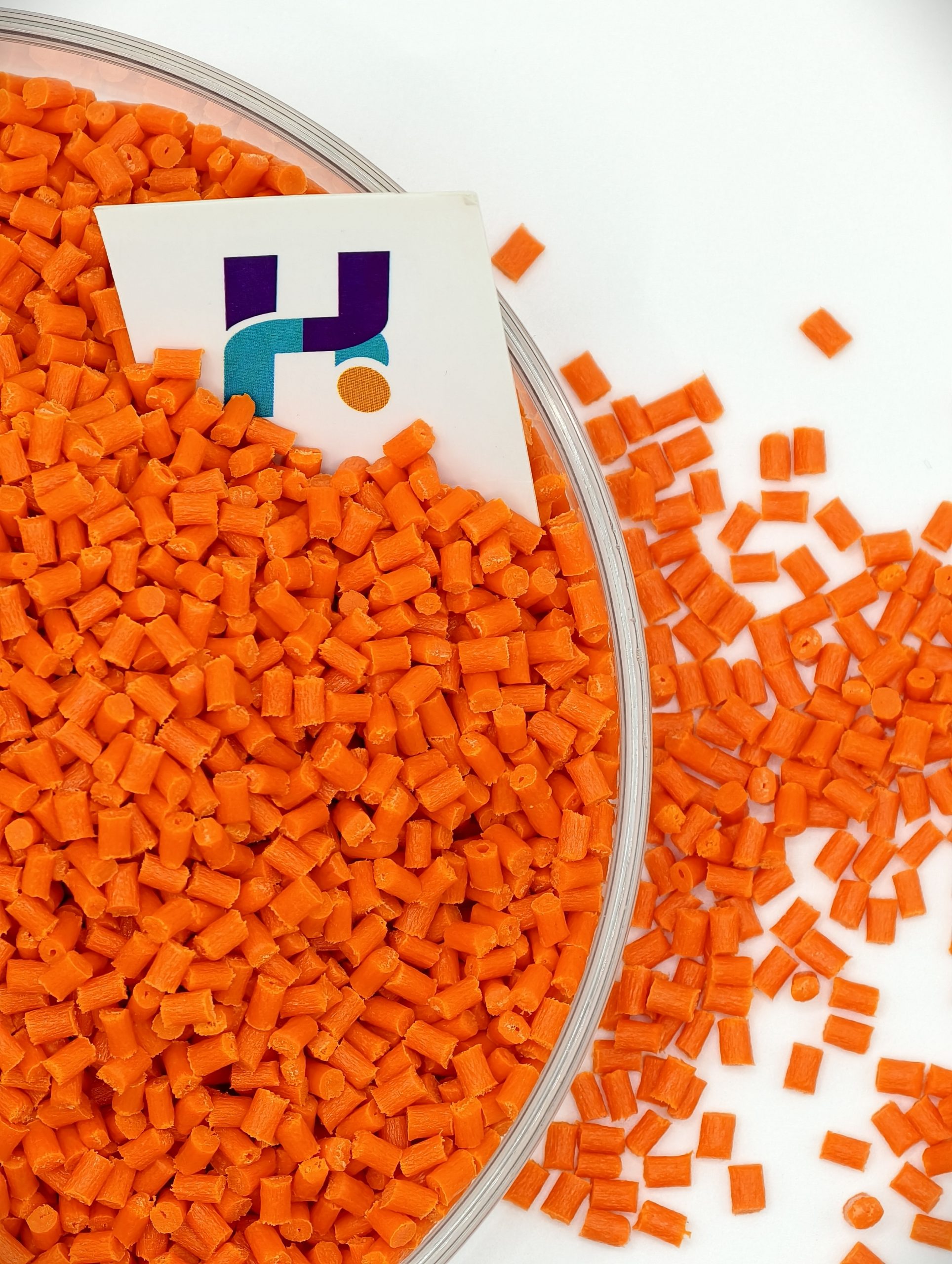
30% glass-fiber reinforced PBT pellets engineered for stable terminal geometry, heat resistance, and repeatable molding in electrical contactors.
A contactor housing looks like a simple shell—until you try to keep it stable across real production: multiple cavities, tight terminal tolerances, insert/fastener stress, and heat generated by switching. In this category, “strong enough” isn’t the goal. The goal is:
-
stable terminal alignment and assembly fit
-
stable creepage/clearance geometry
-
reliable insulation performance over time
-
resistance to heat aging and chemical exposure
-
low variation from batch to batch
That’s exactly where PBT GF30 is typically chosen.
Causes of Contactor Housing Failure
1) Dimensional drift that breaks terminal fit
Small changes in shrink or creep can create big assembly issues: terminals misalign, screws bind, inserts sit proud, or mating parts don’t close cleanly.
2) Heat exposure near switching zones
Contactor housings can see sustained elevated temperatures and repeated heat cycling. Materials that soften or drift create fit instability and long-term reliability risk.
3) Moisture and electrical reliability concerns
In electrical parts, moisture-related dimensional change and insulation stability matter. PBT is often chosen because it is less moisture-sensitive than PA materials in many designs.
4) Warpage in long walls / rib-heavy shells
Multi-cavity tools amplify warpage differences. If the housing is not flat, you lose assembly stability and creepage/clearance confidence.
5) Weld-line weakness at snaps and bosses
Complex flows create knit lines. If toughness and processing are not balanced, snaps and bosses crack during assembly or after aging.
Yongjinhong PBT GF30
PBT GF30 is Polybutylene Terephthalate reinforced with ~30% glass fiber, compounded for injection molding.
Why PBT is a classic electrical housing polymer
-
Excellent dimensional stability and low moisture influence compared with many nylons
-
Heat stability suitable for electrical environments (grade-dependent)
-
Good chemical resistance to oils/greases/cleaning agents common in industrial settings
-
Reliable electrical insulation behavior for housings and terminal structures
What GF30 adds
-
Higher stiffness → housing holds geometry around terminals
-
Better creep resistance → screws and inserts stay stable
-
Improved deformation resistance under heat and assembly load
-
More anisotropic shrink sensitivity → needs gate/cooling discipline for warpage control
Core Selling Points
1) High rigidity for stable terminal geometry
Engineering: GF30 increases modulus and reduces deflection.
Buyer value: easier assembly, stable terminal alignment, less sorting/rework.
2) Dimensional stability with low moisture sensitivity
Engineering: PBT’s dimensional behavior is typically more stable vs hygroscopic nylons in many electrical housing applications.
Buyer value: fewer “fit surprises” across humidity changes and storage time.
3) Heat aging resistance for switching environments
Engineering: PBT GF30 holds shape better under elevated temperatures than many commodity plastics.
Buyer value: reduces long-term drift, protects reliability and compliance margins.
4) Warpage control route for mass production
Engineering: shrink-balance compounding + process stability reduces cavity-to-cavity variation.
Buyer value: calmer production, faster ramp to stable output.
Typical Applications in Contactors
|
|
|
|


-
contactor main housings / shells
-
terminal carriers and insulation frames
-
coil bobbin-adjacent structural parts (design-dependent)
-
covers and internal structural partitions
Performance Target Map
Actual values depend on formulation, color, and test standards.
| Attribute (contactor needs) | Unfilled PBT | PBT GF30 | Why it matters |
|---|---|---|---|
| Rigidity / modulus | Medium | High | stable terminal geometry |
| Creep resistance | Medium | Improved | screw/insert stability |
| Dimensional stability (humidity) | Good | Very Good | less fit drift |
| Heat deformation resistance | Good | Better | hot-soak stability |
| Warpage sensitivity | Medium | Medium–High | gate/cooling discipline |
| Surface fiber signature | Low | Higher | cosmetic strategy if visible |
Engineering Notes That Decide Mass-Production Success
A) Gate & fiber orientation decide warpage direction
At GF30, fiber orientation becomes a major variable. For housings:
-
avoid placing knit lines at snap roots or terminal stress zones
-
balance flow to reduce one-direction shrink dominance
-
prioritize uniform cooling over “higher packing pressure”
B) Insert/screw boss design matters as much as resin choice
Most contactor housing failures happen at bosses and inserts:
-
avoid sharp transitions; keep fillets and rib rules disciplined
-
tune packing to avoid stress locking
-
choose a grade with weld-line and boss durability focus if needed
C) Electrical safety requirements may require FR versions
If your project needs UL94 V-0 (and thickness targets), consider:
-
FR PBT GF30 route (flame-retardant reinforced)
-
thickness-dependent performance planning
-
documentation and compliance package support
Processing Notes
PBT GF30 runs well when the process is stable.
Practical starting points:
-
Drying: recommended to protect surface and properties
-
Mold temperature: keep stable (PBT behavior benefits from controlled mold temp)
-
Injection speed: medium-to-high to avoid hesitation and knit-line weakness
-
Venting: critical for long walls to prevent burn marks and short shots
-
Packing: repeatable; tune for shrink control without locking in stress
QC checks that matter:
-
terminal datum dimensions and flatness fixtures
-
boss integrity check after torque
-
knit-line screening at high-stress features
-
lot-to-lot tracking: flow index + key shrink indicators
OEM Customization Options
Keep this section simple and high-converting:
-
Low warpage route (flatness + terminal geometry focus)
-
Weld-line durability focus (snaps/bosses, high-stress zones)
-
Thin-wall flow tuning (compact housings, multi-cavity tools)
-
Heat-aging stability package (thermal cycling confidence)
-
FR version available (e.g., UL94 V-0 thickness targets, project-defined)
-
Color control (black/gray, lot stability)
What you should provide
No sensitive info needed—just engineering facts:
-
housing wall thickness range + largest flow length
-
target critical dimensions (terminal datums, flatness zones)
-
assembly features: snaps, bosses, inserts, screws
-
main pain point: warpage, boss cracking, snap breakage, short shots, burn marks
-
heat exposure notes (hot-soak, cycling)
-
flame requirement if any (UL94 rating + thickness target)
-
color requirement (black/gray/custom)
If you only provide thickness + flame target (if required) + failure mode + photo, we can start immediately.